Topic
Topic: I am studying 3d prototyping and how it can benefit architecture through 3d functional systems
Question: Because I want to find out how printing 3 dimensionally can better illustrate the functionality of a building system and how it works.
Significance: In order to improve design communication through a medium of 3d components that visually show what the imagination of the designer is.
Goals
My goals for this project are to start by understanding Makerbot as a 3-d prototyping machine, what its capabilities and its limitations are. How I want to better understand Makerbot is by constructing a Hand Crank fan with some simple parts so I can test the printer out and better understand the process from modeling to printing. Once I completely understand the functionality of Makerbot and its process I want to design a wall section with an operable window system, this window system will be constructed out of multiple materials but some components of the model will have to be constructed from the 3-d printing machine. By doing this the wall system will help demonstrate to a client how and why 3d printing needs to be utilized in the design phase for better understanding of how multiple components of a building would be constructed and how they would function
Research examples on how 3d prototyping is relevant to architecture
Manufacturing Processes for Design Professionals. Rob Thompson. London: Thames & Hudson 2007.
This book explains the influences of computing on contemporary design and manufacturing through rapid prototyping. But it explains how “rapid prototyping is good but not comprehensive”.
Measuring for Success, Integrate the Methods associated with Digital Fabrication into their practices.
HPA Architects Bahai Temple
Computer model was first developed through MAYA. MAYA is a software animation industry. Using the program CATIA and a special plug in called Digital Project design by Gehry Technologies, HPA architects were able to use this program to help them model there temple leave structure. Simliar to 3-d Printing machine which prints layer by layer NPA used a CNC milling machine. This machine starts with a block of alabaster in this case and cuts away from the alabaster until the final product is revealed. NPA’s main reason for cutting multiple pieces out of alabaster at a 1:6 scale was to get a more specific prices range of how much the materials labor and Miscellaneous would be for the project. In the conclusion it helped the architects better relate there drawings and ideas to the client and builders, resulting in more accurate prices estimates and a better understanding of the structure of the model and fabrication process.
The Michal Lee-Chin Crystal in the new ROM, Toronto
Another example of using digital fabrication to manage a design concept to completion is at the “renaissance” of the Royall Ontario Museum. Daniel Libeskind wanted to design and model in form –Z before he ever worked in physical models. He wanted to do this at multiple scales to better understand the programmatic requirements of his project. His overall structure is a dia-grid giving the “Crystal” element of the ROM’s renovation multiple load paths. This would allow for the interior of the crystal to have more open space on the interior eliminating interior columns. Because of working with a scaled down prototype model Daniel was better able to understand the structure of the ROM and understand the maximum space allowed for the least amount of supporting structure.
Remodeling a Hand Crank Fan
Continuing from my last blog, where I had modeled a hand crank in Google Sketch up and I then attempted to print this model out using Makerbots 3d printing machine. This had failed because of the dimensions I was making the hand Crank fan out of. The dimensions were too small for the 3-d printer to comprehend, and when printed would come out a blob of plastic.
 |
| First attempt of hand crank in Google sketch up |
So what I did was remodeled the hand crank fan into Revit and then converted it to 3-ds Max. By modeling it in Revit first it would come out more accurate making it easier to print.
 |
| Second and Final attempt of hand crank |
The process
After I modeled it in Revit I then had to select one component that would be printed by. For example I selected the gears. I then exported the gears out of Revit as an FBX file.
 |
| Revit file gears |
I then imported this file into 3-Ds Max.
 |
| Imported Selection of Gears |
Something very important that I learned after importing it into Max and before exporting was once imported into max the selection must be centered in the program vertically and horizontally. Without practicing this you will have multiple problems getting the file to print or even getting the selection to scale or move correctly.
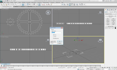
Once center on the platform in 3-ds Max I selected the gears and exported them as a STL file and saved it as a Binary Project.
 |
| Exporting out of 3-Ds Max as a Binary File |
Now using the program Replicator G I imported the saved STL file.
To get the scale right you have to change from metric to standard since Replicator G is a Metric based program
 |
| Imported gears into Replicator G |
Since I built my Hand crank Fan in 1”=1’ I have to convert the model from down.
Once I do this I then go the move button and make sure the file is centered and sitting on the top of the platform.
Next I generate the building code.
These are the setting that worked best for me when printing. Don’t use a rafter, it just wasted plastic and can potentially ruin your model when trying to detach it. Don’t use exterior supports, they can ruin the model when trying to detach them once the model is built. There is almost always a way to build what a model without supports it might take longer but it will help in the long run. Set your infill to 75%, on models with little structure or infill needed. By doing this it will ensure your model will stay cleaner and have less mess ups while its being printed, when the infill is set to 100% the plastic ends up getting in the way on post layers and can also cause a longer print time. Set your shells to 2-3 shells. It will help your model to read better and more fool when it’s finished printing, and it also increase the strength of the model.
 |
| Replicator G code generator |
After the code is generated I then printed my selection.
When first printing the gears I ran into some problems with scale and 3-Ds Max but these problems I have already mentioned how to fix in my blog.
 |
| Failed attempt to print gears |
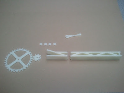
Here are the Final gears and other component of the hand crank that I was able to print out. They came out the right scale and they were also were very accurate considering previous prints.
 |
| Hand Crank components |
Everything went great except for the fact that I ran out of plastic to print with, so half of the Hand Crank fan was not able to be printed.
Final Project, wall section with operable window system
Now that I better understand the process from Revit to Makerbot. I can build my operable window system. This system will be constructed mostly form other materials but there will be some materials that cannot be modeled by hand and will need to be printed off by the 3D printer. Because of the issue of having no plastic to print with this wall section will be put on hold until then.
Here is what the Wall section will look like and how it will operate.
 | |||||
| Operable wall section in Revit |
 |
| Wall section Revit |
This wall section will show how 3-D printing can be relevant to architecture. It will show how the designer can better demonstrate his thought process through a functioning 3-dimensional model, therefore helping the client to fully understand what is being demonstrated with little questioning to the designer
Conclusion
In Conclusion I was able to accomplish my goals of understand Makerbot and how it can be relevant to architecture. I had multiple problems along the way with getting it to print, the accuracy of the printing and importing and exporting between files. Overall I have learned a lot more about Revit and how it’s compatible with 3-Ds max and replicator G. In the future I would further like to show how more relevant 3-D prototyping can be to architecture on a greater scale and with bigger projects.


